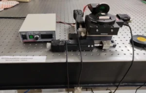

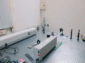
Z-scan technique is used to measure the nonlinear optical properties of materials. The Z-Scan helps to determine intrinsic photo-physical properties of materials by focusing a single laser beams onto the surface of the materials sample. The laser beam is directed perpendicular to the plane of the sample. The sample is moving along the z direction (the laser beam propagation direction) in and out of the laser focal point. The transmitted signal goes either directly to a detector or through an aperture to a detector. The magnitude of the detected signal is plotted as a function of the sample position.
“Open aperture” measurement allows determining the nonlinear absorption of the material. Whereas in the “closed aperture” measurement, the magnitude and sign of the nonlinear index of refraction resulting from the Kerr effect can be determined. Changes in the nonlinear index of refraction lead to nonlinear distortions of the beam. A positive Kerr effect leads to self-focusing of the laser beam. A negative Kerr effect leads to defocusing. Usually, measurements need to be taken at different laser pulse energies or different laser pulse lifetimes in order to determine what nonlinear processes are present.
Research Purpose- Z-scan measurements are a technique for measuring the strength of the Kerr nonlinearity of a material, relying on self-focusing
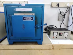
The Bridgman technique (also known as Bridgman Stock Barger method) is one of the oldest techniques used for growing crystals. In Bridgman technique, the crucible containing the molten material is translated along the axis of a temperature gradient in a furnace. In Stock Barger technique, there is a high-temperature zone, an adiabatic zone and a low- temperature zone. Stock Barger’s modification of the Bridgman technique allows for better control over the temperature gradient at the melt crystal interface. This is the most important and widely used method of crystal growth
Specifications:- TRMC-15000C MOS12 Furnace Control Unit
- Translational and Rotational Motion System for Crystal Growth
- In this technique no impurities are introduced in the growth process and the rate of growth is normally much higher than that possible by other methods.
- This is the most important and widely used method of crystal growth.
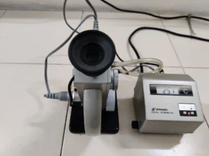
Abbe refractometer is a widely used bench-top device for the high-precision measurement of an index of refraction. Refractive index is an important optical constant used to determine the optical performance of the material. Working principle of Abbe refractometer is based on critical angle. Sample is put in between two prisms, measuring and illuminating prisms. Light enters into the sample from the illuminating prism, gets refracted at critical angle at the bottom surface of measuring prism, and then the telescope is used to measure position of the border between bright and light areas, from which the refractive index of the material will be obtained.
Specifications: Make : ATAGO, NAR-4T Range : 1.4700 to 1.8700 Accuracy: ±0.0002 Temperature range: 5 to 50゚C Research Focus:- To identify the sample by comparing its refractive index to known values
- Assess the purity of the sample by comparing its refractive index
- To find the thickness of the film using refractive index
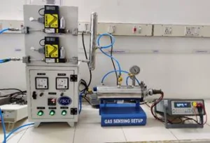
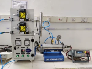
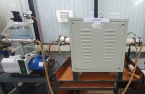
Gas Sensor testing unit is a system designed to reproduce environmental conditions in which a Gas Sensors device will be operated. In this gas sensor unit, argon and nitrogen can be sensed. This furnace is suitable for operating under multiple gaseous environments. Sensors based on metal oxide semiconductors are mainly applied to detect target gases through redox reactions between the target gases and the oxide surface. Initially through redox reactions, the O− distributed molecule on the surface of the materials will react with molecules of target gases, leading to an electronic variation of the oxide surface and then this variation is transduced into an electrical resistance. LabVIEW software is the interface used to get the output data. Output result will be obtained as a graph between Time Vs Sample Temperature and Time Vs Resistance.
Specifications:- Make: VB Ceramic consultants
- Shell design: Suitable for vacuum and pressure (1mbar)
- Maximum temperature: 600°C (accuracy ±1°C)
- Rotary vacuum pump (10-1 mbar)
- Mass flow controller
- To sense the presence of Argon and Nitrogen gases in the atmosphere
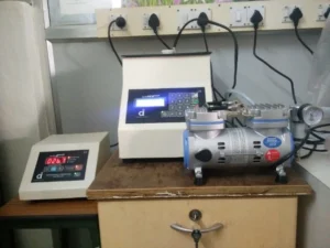
Spin coating is the simplest method for fabricating a film on a substrate. Thin-resist layers for photolithography are coated with this technique. The spin-coating process starts with the dilution of the material to be deposited in a solvent. The solution is subsequently dispensed on the substrate surface. The wafer is then spun at a high speed. The thickness of the film is determined by the spinning speed, surface tension, and viscosity of the solution. The solvent is removed partly during the spinning process due to evaporation and partly by subsequent baking at elevated temperatures. Spin coating results in a relatively planar surface. This technique is often used for planarization purposes.
Specifications:- Make and Model: Apex-spin NXG-ACH
- Spin coating unit with vacuum pump and heater
- Programmable digital process controller for repeatable, accurate processing
- Maximum 10000 rpm
- Ferrite thin films for recording media applications
- Gas sensors
- Organic Solar cells
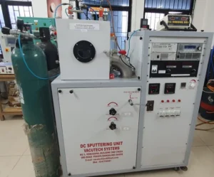
Magnetron sputtering is extremely basic and useful tool to deposit thin films. The high voltage is applied to the sputtering gun which ionizes the sputtering gas. These high energy ions create gaseous plasma when bombarded on the target material to be deposited. The gaseous plasma contains the material to be deposited. The atoms travel in vacuum and deposited onto a desired substrate to form a thin film of target material. One can tune the sputtering pressure, substrate temperature to get the optimized thin film.
Specifications:- Brand: VacuTech Systems
- Two sputtering guns (DC and RF)
- Maximum power 300 W
- Temperature: 500 oC
- Base pressure: 1 × 10⁻⁶ mTorr
- Thin films for solar cell application
- Metal electrode deposition
Instrument BCS 805 series battery cycling system is a modular system that addresses the expanding needs in testing the battery cycling efficiency. The module is composed of 8 channels and ensures better accuracy in current control and measurement with 5 current ranges. It has an 18 bit analog to digital converter for the voltage measurement. This instrument is capable of working over a frequency range from 10kHz to 10mHz for accurate and fast determination of the battery internal resistance. This instrument allows for temperature measurement with K-type thermocouple.
Specifications:- High quality EIS: full scan from 10kHz to 10mHz
- 18-bit A/D converter
- HPC measurement down to 6.3ppm
- Modularity from few mA to 120A
- Voltage measurement from 0 – 9V
- 2ms acquisition time
- Impedance studies
- Electrochemical characterization
Electrochemical workstation provides various analytical techniques such as cyclic voltammetry, chronoamperometry, differential pulse voltammetry, linear sweep voltammetry, square wave voltammetry, etc. windows based software and integrated digital CV simulator and fitting, impedance simulation and fitting program. It is a powerful tool to understand fundamental aspects of electrochemical kinetics and trace level analysis.
Specifications:- BMake: CH Instruments, Austin, Texas.
- Electrode configuration: 2 or 3-electrode system
- Model: CHI620E
- Maximum potential: ±10 V
- Maximum current: ±250 mA
- To obtain the redox potentials of molecules and materials
- To monitor the electrode stabilities in various pH
- To get HOMO-LUMO energy details for NLO and DSSCs chromophores
Ball milling (solid-state synthesis) is one of the most important processes used in industry to synthesize nanomaterials, and is also called mechanical alloying or attrition. This method is based on a top-down approach, like self-assembly of molecules and reducing the size of the larger particles. The principle involved in the milling process is the generation of frictional force due to the collision between the reactants’ surface, which leads to increased temperature, pressure, and internal energy.
Specifications:- Brand: Nanotech
- Tungsten carbide vial and balls
- Maximum 300 rpm
- Nanomagnetic and Nanocomposite materials for permanent magnet applications
- Magnetocaloric Materials
- Dilute magnetic semiconductor
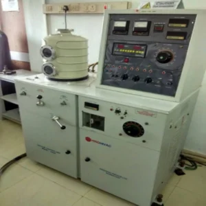
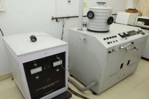
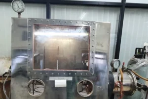
The vacuum thermal evaporation deposition technique is one of the simple thin film coating techniques. The equipment has vacuum coating unit Model: 12A4D. The system is capable of producing an ultimate vacuum of 5×10− 6 mbar. The vacuum chamber was pumped with a diffusion pump and a rotary pump combination. The pressure in the vacuum chamber was measured using digital Pirani and Penning gauge combination. In this, only one filament is used at a temperature sufficiently high to evaporate even the less volatile material instantaneously. In this method, very small grains of the evaporant alloys are dropped sequentially into the hot boat which immediately vapourize to form a condensate on a nearby heated substrate, ensuring the stoichiometry of the films. This technique allows an excellent control over various deposition parameters to get good stoichiometric films.
Using this technique, the metal and semiconductors in elementary form or compound form can be prepared as thin films. Generally the materials which have low melting points can be prepared as thin films onto the glass or quartz substrates. Various metals such as indium, tin, zinc, cadmium, aluminum, etc are prepared as thin films and annealed in air to prepared indium oxide, zinc oxide, cadmium oxide, etc. Further the compound materials such CZTS or CIGS were also prepared as thin films for solar cell applications. It can deposit both metals and nonmetals, including aluminium, chrome, gold, indium, and many others. This method of evaporation can be applied to deposit metallic contact layers for thin film devices such as OLEDs, solar cells and thin-film transistors.
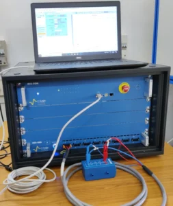
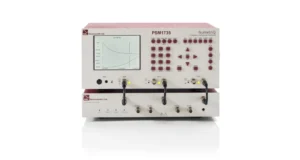
A phase-sensitive multimeter meter is an electronic device capable of measuring the inductance (L), capacitance (C) and resistance (R) of a device under test when applied AC voltage. The combination of LCR measurement help to calculate the effective series resistance (ESR), Q-factor, dissipation factor (tanδ) and phase angle. The measurement of C-R for the device under test is performed usually in-between the parallel plates where the capacitance in parallel (Cp) and resistance in parallel (Rp) is measured. In this work, the measurement of dielectric constant and dissipation factor of the samples was done using PSM-1735 LCR active head with Impedance Analyzer Interface (IAI) (Newton’s 4th –N4L) under a broad frequency (10 Hz to 10 MHz). The operation procedure for measuring the electrical parameters is further explained. The sample with a diameter of 1.8 cm. was inserted into the fixture (brass electrode) and placed into a dry temperature calibrated furnace. The electrode was then connected to PSM-1735 LCR active head which is interfaced with the computer. The fetched data was used to plot the graphs for ε’ and (tanδ) and studied.
Research Focus:Research works on dilute magnetic semiconductors and transparent conducting oxides are being carried out in this lab. The materials such as In2O3, SnO2, ITO, ZnO, ZnS, CdTe, zinc ferrites were synthesised and studied for their physical properties. Various impurity elements such as Fe, Mn, Ni, and Cu were doped into the In2O3 host material and studied their physical properties. Similarly the elements such as Ni, Fe and Cr were doped into the SnO2 and studied their physical properties. Also pure and transition metal oxides were substituted into the ITO and studied their magnetic properties. The zinc ferrites were prepared using chemical methods and studied their dielectric and magnetic properties. It was found that
- In2O3 exhibited room temperature ferromagnetism
- SnO2 exhibited room temperature ferromagnetism
- Indium tin oxide also found as room temperature ferromagnetic material
- ZnS exhibited weak ferromagnetism at room temperature
Electron beam evaporation is one of the thin film deposition methods where the direct transfer of energy with the electron beam to the target material to be evaporated making it ideal for metals with high melting points. By concentrating the energy on the target rather than the entire vacuum chamber, it helps reduce the possibility of heat damage to the substrate. And multiple thin film can be deposited sequentially without breaking vacuum and can deposit thinner films with higher purity. The equipment Electron beam Gun power supply Model: EGC-3KW has HT and LT transformer, HT inductor, bleeder resistor and with this, at the top controlling unit consist of the voltage and current stabilizer with all the other controls to operate the gun is provided. Beam voltage indicated on two wide view meters provided with 0 to 10 KVDC meter (calibrated on 0-500 micro amp meter) for voltage and 0 to 500 mA DC meter for emission current. And the power supply can connect with Vacuum unit for deposition of thin film. Which consists vacuum chamber and pumping system.
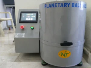
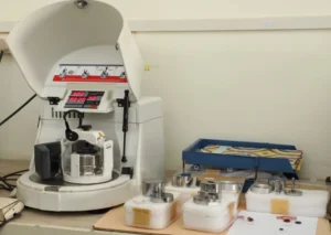
The comminution of the material to be ground takes place primarily through the high-energy impact of grinding balls. To achieve this, the grinding bowl, containing the material to be ground and grinding balls, rotates around its own axis on a main disk whilst rotating rapidly in the opposite direction. At a certain speed, the centrifugal force causes the grinding of the sample material and grinding balls to separate from the inner wall of the grinding bowl. The grinding balls then cross the bowl at high speed and further grind the sample material by impact against the opposite bowl wall. In addition, impact between the balls themselves on the sample material adds to the size reduction process. Due to the enormous rotational speed of the main disk – up to 650 rpm – achieves the PULVERISETTE 6 classic line a centrifugal acceleration of up to 29 g.
The Planetary Mono Mill PULVERISETTE 6 classic line is a high-performance Planetary Ball Mill with a single grinding bowl mount and practical, easily adjustable imbalance compensation. Your advantage: Particularly easy use and high-energy effect of up to 650 rpm. This ensures a constantly high grinding performance with extremely low space requirements for loss-free grinding results for the comminution of hard, medium-hard, brittle and moist materials, dry in suspension or in inert gas. At same time, the PULVERISETTE 6 classic line is ideally suited for mechanical alloying or for mixing and perfect homogenising of emulsions and pastes.
Specifications:- Make: Fritsch mono mill
- Model: PULUERISETTE-6
- Speed: 650 rpm
- Ceramics
- Metals, Dilute magnetic semiconducting materials
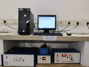
Ferroelectricity is a characteristic of certain materials that have continuous electric polarization that can be reversed by the application of an external electric field. All ferroelectrics are pyroelectric, with the additional property that their natural electrical polarization is reversible. The term is used in analogy to ferrimagnetism, in which a material exhibits a permanent magnetic moment. When most materials are polarized, the polarization induced, P, is almost exactly proportional to the applied external electric field E; so, the polarization is a linear function.
Specifications:- Brand: Marine India
- Maximum Field: +5KV/(50KV/cm)
- Frequency Range: 20Hz – 1 KHz
- Cryogenic Temperature Stage: 100RT (96K – 273K)
- Sample Dimension: 2- 10 mm diameter
- Nature of the materials
- Fatigue measurement
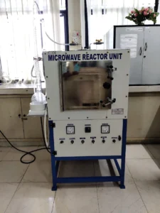
Microwave heating is a multi-physics phenomenon that involves electromagnetic waves and heat transfer; any material that is exposed to electromagnetic radiation will be heated up. The rapidly varying electric and magnetic fields lead to four sources of heating. Any electric field applied to a conductive material will cause current to flow. In addition, a time-varying electric field will cause dipolar molecules, such as water, to oscillate back and forth. A time-varying magnetic field applied to a conductive material will also induce current flow. There can also be hysteresis losses in certain types of magnetic materials. Utilizing microwaves for sintering materials saves lot of energy and time. Further ensures volumetric and homogeneous heating without thermal stresses.
Specifications:- Make: V. B. Ceramics Pvt. Ltd.
- Model: Dual magnetron model
- Temperature: 1200oC
- Magnetic ceramics
- Ferroelectrics
- Piezoelectric materials
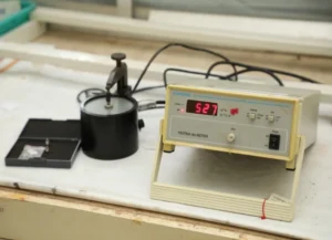
d33 is one of the most useful measurement in estimating the piezoelectric nature of the material. The instrument directly measures the charge accumulated on the end faces per unit force applied. The instrument can measure d33 values for ceramics, polymers and single crystals. The meter can measure the d33 in various crystal directions of a single crystal sample. The meter can give the d33 reading for a variety of sample size and shapes like pellet, toroids, spheres, disks, cylinders, semi spherical shells etc.
Specifications:- Make: Sinocera
- Model: YE2730
- Range: 10 to 2000 pC/N
- Ceramics viz ferroelectrics, piezoelectrics like BT, PZT, BCT-BST
- Single crystals like lithium niobate, quartz, tourmaline, silver niobate and
- Polymers of PVDF family
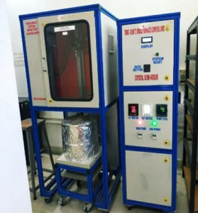
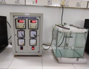
Sankaranarayanan–Ramasamy (SR) method is used to grow bulk crystals with specific orientation. This SR method is a suitable method to effectively control the orientation of molecules during the bulk crystal growth from solution at room temperature with 100% solute to crystal conversion efficiency. Unidirectional crystals are very important for the preparation of functional crystals. For example, the conversion efficiency of second harmonic generation is always highest along the phase-match direction for nonlinear optical crystals, in such cases unidirectional crystal growth method is the most suitable to grow bulk sized crystals along that particular direction. The experimental setup consists of two ring heaters, transparent glass tubes made by borosilicate glass and seed mounting pad. The ring heaters are positioned in the top and bottom of the ampoule. The heaters are connected to a dual channel temperature controller which maintains constant temperature. The entire setup is kept in a water bath. The experimental setup was placed in a dust-free hood.
Specifications:- Make: Gemini Scientific company
- Two ring heaters
- Temperature range: Room Temperature (RT) – 100°C
- Dual channel Temperature controller
- Unidirectional crystal growth
- Growth of Organic and Inorganic single crystals
- NLO and scintillation single crystal
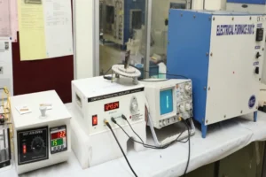
The crystal oscillator circuit sustains oscillation by taking a voltage signal from the quartz transducer, amplifying it, and feeding it back to the resonator. The rate of expansion and contraction of the quartz is the resonant frequency, and is determined by the cut and size of the crystal
Internal friction and modulus are useful probe to examine defects, microstructure and phase transitions as well as important parameters to monitor mechanical behavior. This study focuses a new piezoelectric composite oscillator method for modulus and internal friction measurement. The technique is appropriate to the evaluation of small-size ceramics test piece with 1-3mm thickness, 2-4mm wide and 10-40mm length. This technique can be applied to the measurement at elevated temperatures up to 800°C under direct heat environment without buffer materials.
Specifications:- Make: Mittal Enterprises, India
- Temperature: 30 to 150oC
- Quartz: X-cut
- Ceramics, Bio-ceramics
- Single crystals
- Geological samples
Constant temperature water bath (CTB) is used to maintain uniform temperature throughout the solution contained in a glass container with the accuracy of 0.05º C. A stirrer is used to stirr the water in order to maintain the uniform temperature throughout the water bath. It allows the heating of the solution over a period of time without changing the concentration of constituents by evaporation. It also prevents excessive evaporation of the solution being heated. Constant temperature water bath is used to grow crystals under controlled thermal environment. Since water bath offers superior temperature control, range, and uniformity, it is used in slow evaporation method.
Specifications:- Make: Sub Zero
- Temperature controller
- Two Stirrer to maintain uniformity
- Cooling Unit
- Maximum Temperature – 100 °C
- Slow cooling method for crystal growth
- Slow evaporation technique for crystal growth
- High quality optical crystals
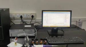
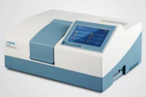
The double – beam spectrophotometer can be used to determine the absorption and transmission spectra within the wavelength range of 190-1100nm with an accuracy of 0.5nm. This spectrometer has the option of selecting the light source between Deuterium Lamp (D2) and tungsten (W) halogen lamp.
Research Focus:- Low dimensional Materials, Optical energy gap calculations.
- Semiconductors material characterisation
- Organic compounds in Biological matter
The spray pyrolysis is one of the techniques which is thin film deposition by spraying a solution on a heated surface. This technique is designed for short time and low-cost thin film formation. Here a compressed carrier gas is blown through the precursor which is sprayed on the substrate at elevated temperatures.
Specifications:- Custom designed
- Temperature: 300 oC
- Solar cell
- Organic Solar cells
- CuGaS2, Al:ZnO thin films
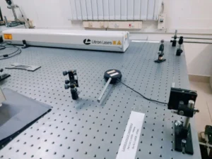
A process of materials that induces residual compressive stresses on the surface of a component due to shock waves produced by plasma”. Laser peening (LP), or laser shock peening (LSP), is a surface engineering process used to impart beneficial residual stresses in materials. Laser peening uses the dynamic mechanical effects of a shock wave imparted by a laser to modify the surface of a target material. Fundamentally, laser peening can be accomplished with only two components: a transparent overlay and a high energy pulsed laser system. The deep, high-magnitude compressive residual stresses induced by laser peening increase the resistance of materials to surface-related failures, such as fatigue, fretting fatigue and stress corrosion cracking. Laser shock peening can also be used to strengthen thin sections, harden surfaces, shape or straighten parts (known as laser peen forming), break up hard materials, compact powdered metals and for other applications where high pressure, short duration shock waves offer desirable processing results.
Specifications:- Brand-Litron Lasers
- Laser medium: Nd-YAG Laser
- Energy – 400 mJ
- Laser Wavelength – 1064nm
- Pulsed duration – 6ns
- Surface Distribution of Residual Stresses
- Thermal stability of Residual Stresses
- In-Depth Residual Stress Distribution
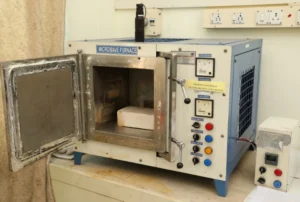
A tube furnace is an instrument which used a cylindrical tube surrounded by electrically heated elements to synthesis inorganic/organic compounds. These elements are connected to a thermocouple and feedback to a PID controller to maintain desired temperature and ramping rate. Here we use a tube furnace to syntheses target materials. The samples can be treated under controlled gas atmosphere/vacuum up to 1000 oC.
Specifications:- Temperature: 1000 oC
- Controlled gaseous environment
- Inorganic compound synthesis
- Heat treatment to the substrates
- Sulfurizing thin films
The laser damage threshold (LDT) or laser induced damage threshold (LIDT) is the limit at which an optic or material will be damaged by a laser given the fluence (energy per area), intensity (power per area), and wavelength. LDT values are relevant to both transmissive and reflective optical elements and in applications where the laser induced modification or destruction of a material is the intended outcome. For long pulses or continuous wave lasers the primary damage mechanism tends to be thermal. Since both transmitting and reflecting optics have non-zero absorption, the laser can deposit thermal energy into the optic. At a certain point, there can be sufficient localized heating to either affect the material properties or induce thermal shock. Dielectric breakdown occurs in insulating materials whenever the electric field is sufficient to induce electrical conductivity. For very short, high power pulses, avalanche breakdown can occur.
Specifications:- Brand: Litron Lasers
- He-Ne Laser-632nm
- Laser cutting
- Pulsed laser deposition
- Certain laser medicine techniques
- Plasma generation, especially for Wakefield acceleration
- Laser weapons
This is a reactor unit where the samples will be exposed to microwaves for treatment purpose.
- 1. Waste oil treatment
- 2. Chemical plasma treatment
- Temperature programmable.
- Power programmable.
- Gas in and gas out.
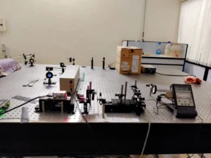
Second harmonic generation (SHG), also called frequency doubling, is a nonlinear optical process, in which photons interacting with a nonlinear material are effectively ‘combined’ to form new photons having twice the frequency of initial photons. It is a special case of sum-frequency generation (2 photons), and more generally of harmonic generation.
Crystal materials lacking inversion symmetry can exhibit a so-called χ(2) nonlinearity. This can give rise to the phenomenon of frequency doubling, where an input (pump) wave generates another wave with twice the optical frequency (i.e. half the vacuum wavelength) in the medium. This process is also called second-harmonic generation.
Specifications:- Laser-Nd-YAG Laser (1064 nm)
- Make-THOR Labs
- Second-Harmonic Imaging Microscopy (SHIM)
- Ultra-Short Pulse Measurement
- Study of Biological Structures and Surface Chemistry